Automated Inspection Using Machine Vision
1. Introduction:
We
have developed several automated inspection systems for industry, as follows:
-
Dr. Gary M. Bone
-
Dept. of Mechanical Engineering
-
McMaster University
-
Hamilton, Ontario, CANADA, L8S 4L7.
-
Phone: (905) 525-9140 ext. 27591
-
Fax: (905) 572-7944
-
e-mail: gary at mcmaster.ca
2. High-Speed Inspection Machine for Automotive Parts
We have developed a machine we developed for a local
company that inspects the bearing surfaces on automotive rocker arms
using machine vision; and then sorts them into reject/accept bins.
Subtle surface defects can be detected, and the machine can inspect
60 parts per minute. The machine is now running in-production at the
customer's facility. Video
of the machine in operation (1.3 meg AVI file using DIVX compression,
the CODEC is available here
or from www.divx.com).
|
The rocker arm inspection machine. |
Detection of a defect (raised metal) on the dimple-shaped bearing surface. |
3. Automated Inspection of Subtle Surface Defects
We
have developed a system incorporating custom lighting and image processing
techniques which is capable of detecting very subtle defects on the
surface of products. These defects can even be difficult for a
person to see under ambient lighting. Examples are shown in Figures
1-4. As these examples demonstrate, the system can successfully
detect subtle defects on flat and curved surfaces. This system was completed
in Sept. 2000 and has been transferred to the end user’s facility.
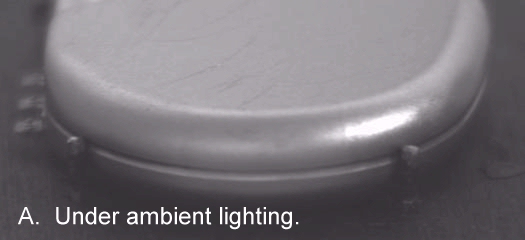
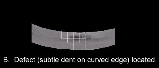
Figure 1: Product with a subtle dent on its curved edge. A: Under ambient lighting. B: Subtle dent located by the automated inspection system.
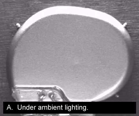
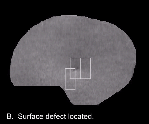
Figure 2: Product with a subtle dent on its flat face. A: Under ambient lighting. B: Subtle dent located by automated inspection system.
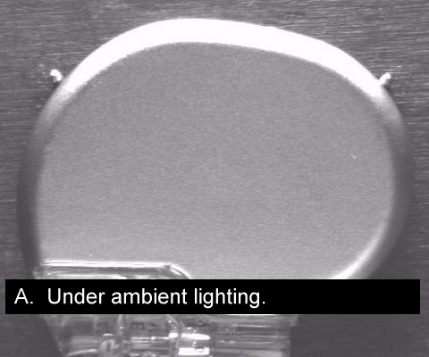
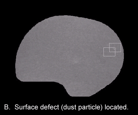
Figure 3: Product with a dust particle near its right edge. A: Under ambient lighting. B: Dust particle located by automated inspection system.
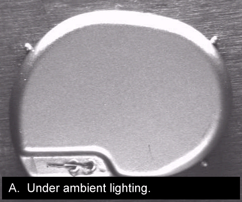
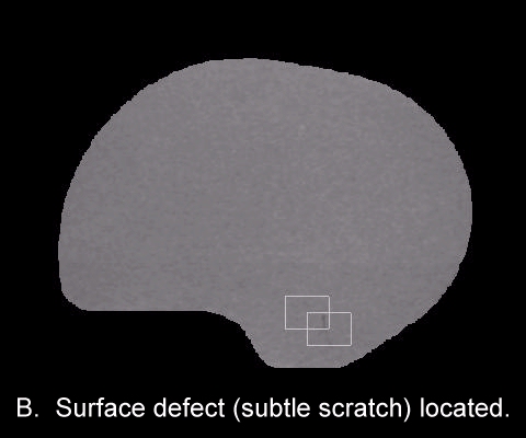
Figure 4: Product with a subtle scratch. A: Under ambient lighting. B: Subtle scratch located by the automated inspection system.
4. Resistance Welding Machine Incorporating Automated Inspection
4.1 Overview
This
machine automated the resistance spot welding of two small wires, a
job previously done manually using a microscope and tweezers.
Part handling, weld power monitoring, and automated inspection systems
were designed and built (including hardware and software). The
machine was PC controlled with a custom user interface.
4.2 Automated Visual Inspection of the Two Welds
The
two welds are shown in Figure 5. The first weld, shown at the
left, involves the connection of a 0.4 mm diameter niobium wire
to a block, and was termed the “block-weld”. The second weld,
shown on the right, involves the connection of two 0.4 mm dia. wires
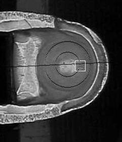
together to form a T shape, and was termed the “T-weld”. A close-up
of a sample T-weld is shown in Figure 6. The welds were inspected
for several dimensional specifications using machine vision. The
primary specifications measured were the penetration of the wire into
the block with the block-weld, and the penetration of the two wires
into each other with the T-weld. This penetration is also known
as embedment. Two sample inspection results for the T-weld are
shown in Figure 7. Some of the dimensions have been overlayed
on the original camera image. The T-weld inspection system involved
custom lighting and image processing software development. The
block-weld inspection system employed the standard laser striping technique
with custom image processing software. A sample result with the
laser stripe shown is given in Figure 8.
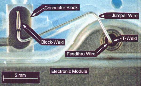
Figure 5. The two resistance welds the machine was built to automate.
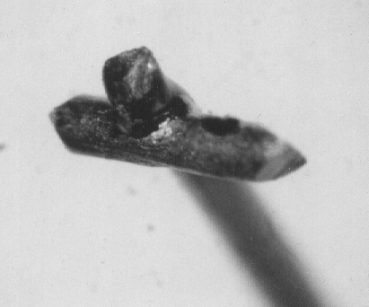
Figure 6. Close-up of a T-weld.
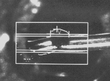
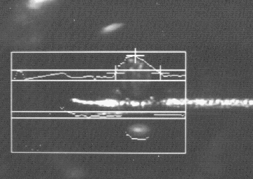
Figure 7. Two Sample automated inspection results for the T-weld. Some the measurements have been overlayed on the original image. (Please Note: These are photos taken of the computer screen at the end-user's facility).
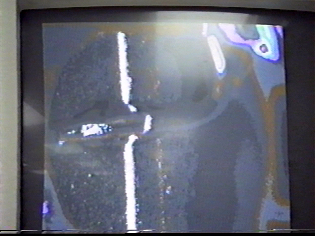
Figure 8. An image taken during the inspection of a block-weld showing the laser stripe. (Photo of the computer screen at the end-user's facility).
4.3 System Construction, Transfer and In-Production Use
The
system was developed at our lab in McMaster University and transferred
to the end-user’s facility upon completion. The system is shown
during the development phase in Figure 9. The system is shown
operating in-production at the end user’s facility in Figure 10.
The system was completed in July 1994 and ran on-line at the end user’s
facility until May 2000 (ending only because the product being welded
was discontinued).
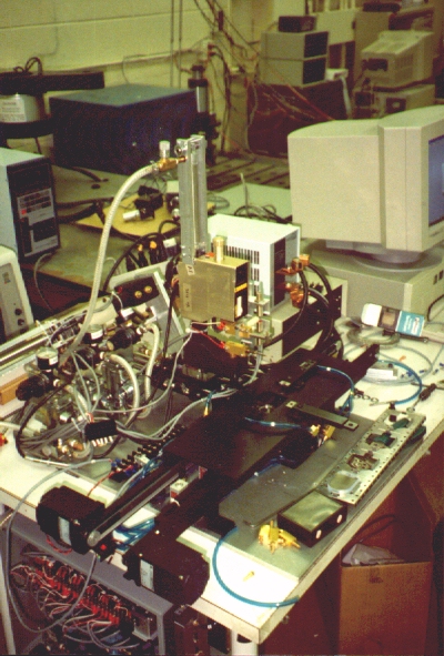
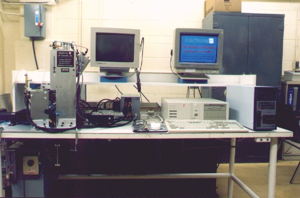
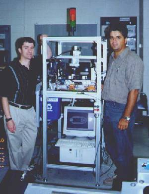
Figure 9. The resistance welding machine during development at McMaster. The motors for the conveyor system can be seen near the bottom left of the left image.
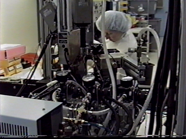
Figure 10. The completed resistance welding machine operating in-production inside the end user's clean room.
5. Laser Welding Machine Incorporating Automated Inspection
5.1 Overview
This
machine automated the laser welding of two formed titanium parts (0.5
mm wall thickness). A 4-axis servo controlled fixturing unit (for manipulating
the parts relative to the stationary laser), and an automated inspection
system (hardware and software) were developed. The machine was PC controlled
with a custom user interface. An existing laser was re-used, again controlled
by the PC.
4.2 Automated Pre and Post Weld Visual Inspection
Since
the laser welding involves no filler metal, the gap between the two
parts must be within a small tolerance to provide a continuous, void-free
weld. The alignment along the seam was measured in the out-of-plane
dimension using the standard laser striping technique while custom image
processing was used to measure the in-plane gap between the parts.
Sample images are shown in Figure 11. If the alignment of
the parts was found to be acceptable by the inspection system the automated
welding was then performed. A post-weld machine vision inspection
was then performed (images unavailable).
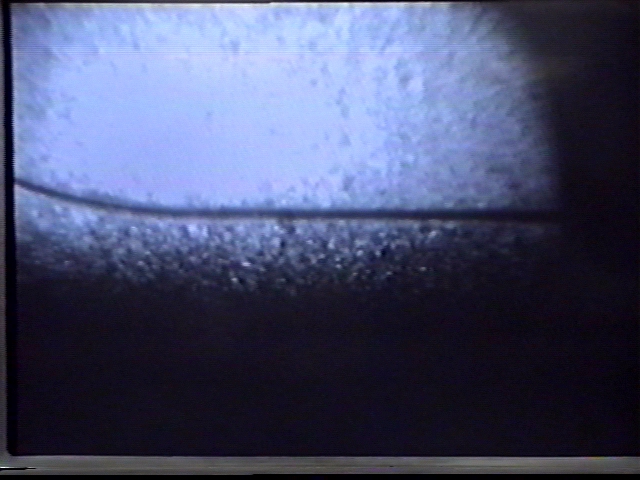
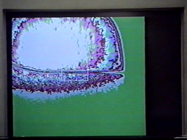
Figure 12. Measurement of the in-plane gap between the parts prior to welding. Left: Original camera image. Right: During image processing. (Please Note: These are photos taken of the computer screen at the end-user's facility).
5.3 System Construction, Transfer and In-Production Use
The
system was developed at McMaster and transferred to the end-user’s facility
upon completion. The system is shown during the development phase
in Figure 13, with the 4-axis servo controlled fixturing unit at the
top, right. The system is shown at the end user’s facility in
Figure 14. The system was completed in May 1994 and continues
to run in-production at the end user’s facility.
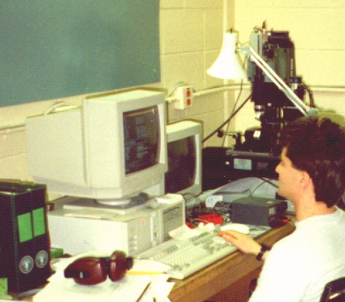
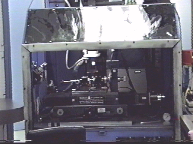
Figure 13 (at left): Laser welding machine during development at McMaster University.
Figure 14 (at right): The automated laser welding machine installed at the end user's facility.
For Further Information Please Contact:
Researchers:
- Dr. Gary Bone, Dr. David Capson, Peter Bender, Lucian Balan, Yan Li, Robert van Varseveld.